Radio Structures BM30 T Base Plate Mods
One area of concern which came to light after the tower went into service was the base plate or more to the point the stress been tranfered from the tower on a windy day to the base post and in turn the base plate. This may prove difficult to explain and harder to follow! but I shall endeavour as I believe it to be an important safety issue.
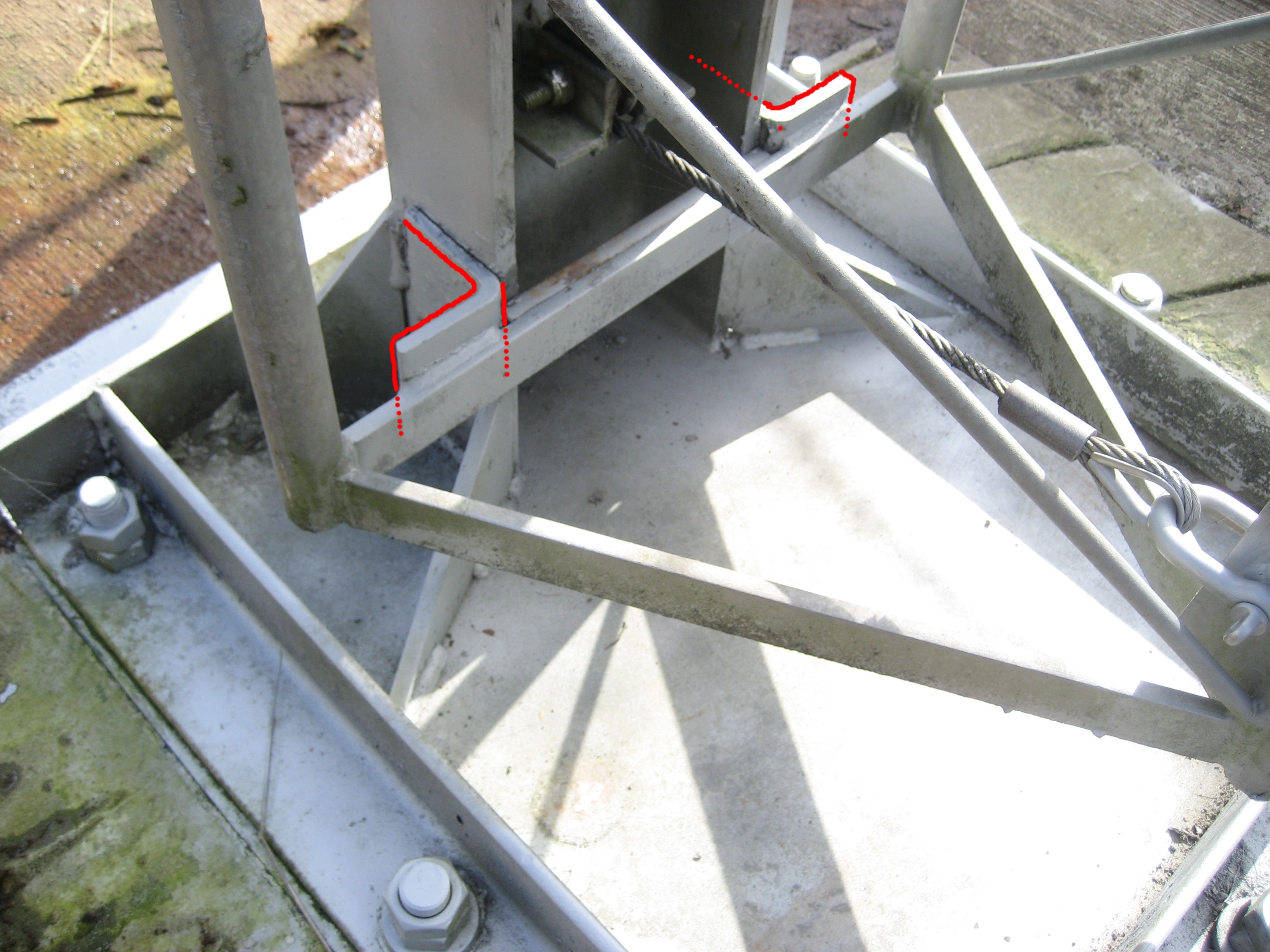
Once again please note that this tower involves 5 sections of lattice and at full height reaches almost 27 meters. As the tower took the antenna load and its own load in the wind the base post was unable to remain completely vertical due to the flexing in the base plate. By design the post is mounted off-center on the base plate and in effect - as the tower moved in the prevailing westerly winds it created a camber inbetween the holding fixtures on the base plate. Depending on the nature of the wind this caused an extremely undesirable movement in other words a rocking motion in the length of the tower. I was of the belief that this rocking to and fro did not allow the tower to take its stress load the correct manner to the base of the bottom section ie - the bottom section was not getting the chance to hold vertical which would allow each section above it to do its work - the whole tower from top to bottom was potentially at an angle or in a lean. I felt that in gusty or squally wind conditions it may be possible for this rocking motion to gain such a momentum that the force involved could put the tower too far beyond its center of gravity, this coupled with the size or lack of size of the gussets lead me to believe that a failure may be possible. It is my opinion that the base plate at 15mm is too thin for the load involved and hence flexing occurs which transferes to the post and in turn on to the tower. I will detail issues with the gusset size further on in this article but firstly I will outline the measures taken in an attempt to eliminate the base plate flex and base post movement. The first action was to cut two lengths of angle 80x80x10, drill them to allow the fixing bolts through and lock them down across each side of the base plate where the flexing was occuring. The result was only a very slight improvement. It was clear that more work needed to be done. After much debate with friends and consultation with a local steel engineer a course of action was decided. This would be two fold in that it would address the initial base plate flex issue ( the rocking of the tower ) and secondly displace a good deal of the stress load from the four gussets at the base of the post. 1, Continue the angle around the base plate, weld for rigidity, drill the angle, base plate and then drill on into the concrete for 500mm. Use Chemical fixing bolts 25mm x 700mm. These bolts were to be placed mid way between each original fixing and then locked down. 2. A much larger piece of angle was to be welded at the front of the base plate this would be locked down in a similiar fashion to create a greater base plate area. |
Click pictures to enlarge
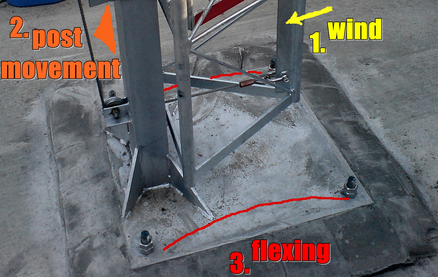
ORIGINAL BASE
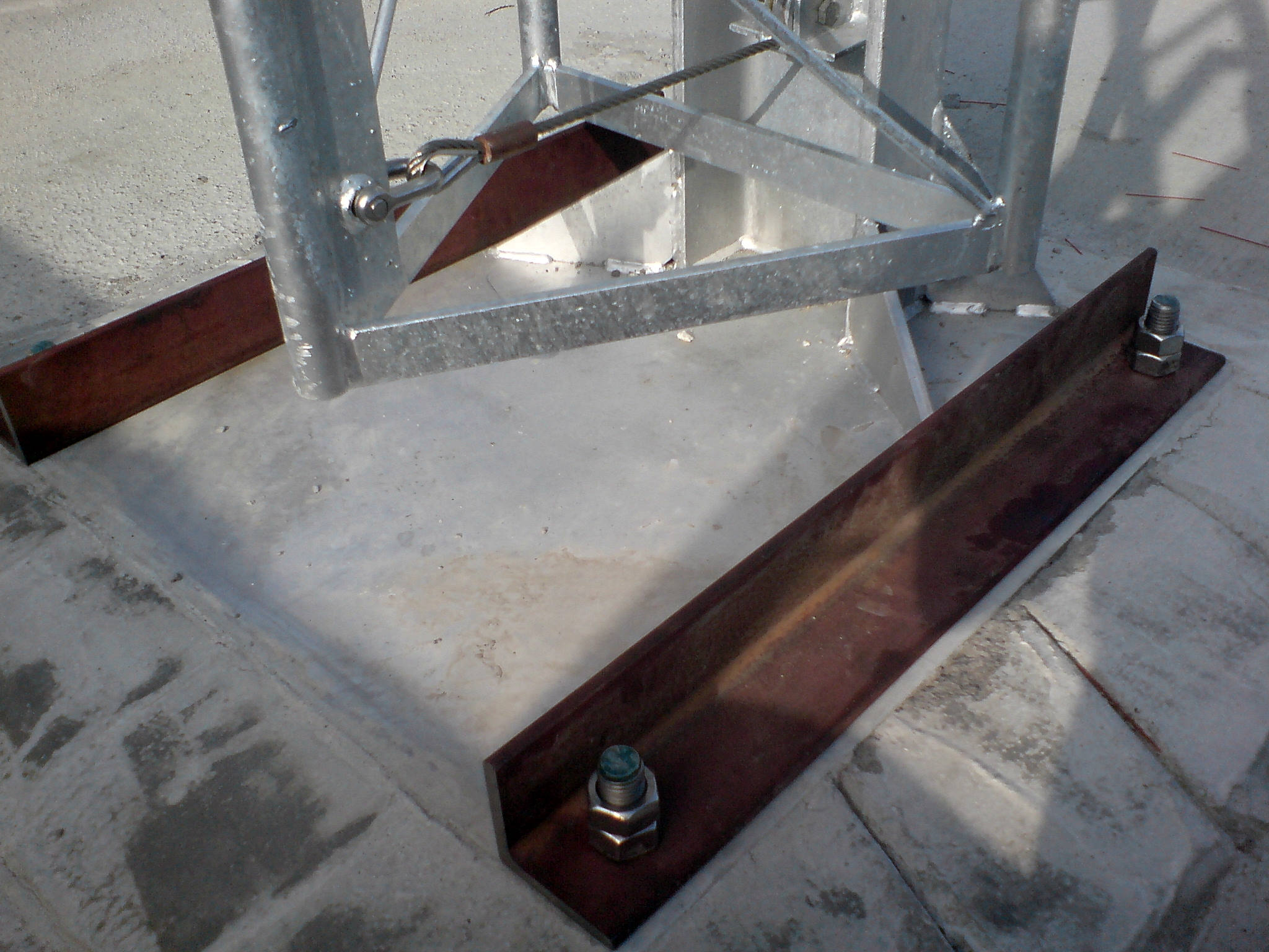
WITH ANGLE ACROSS THE FLEX POINTS
WITH EXTRA ANGLE AND CHEM FIX BOLTS
LARGER FRONT ANGLE
|
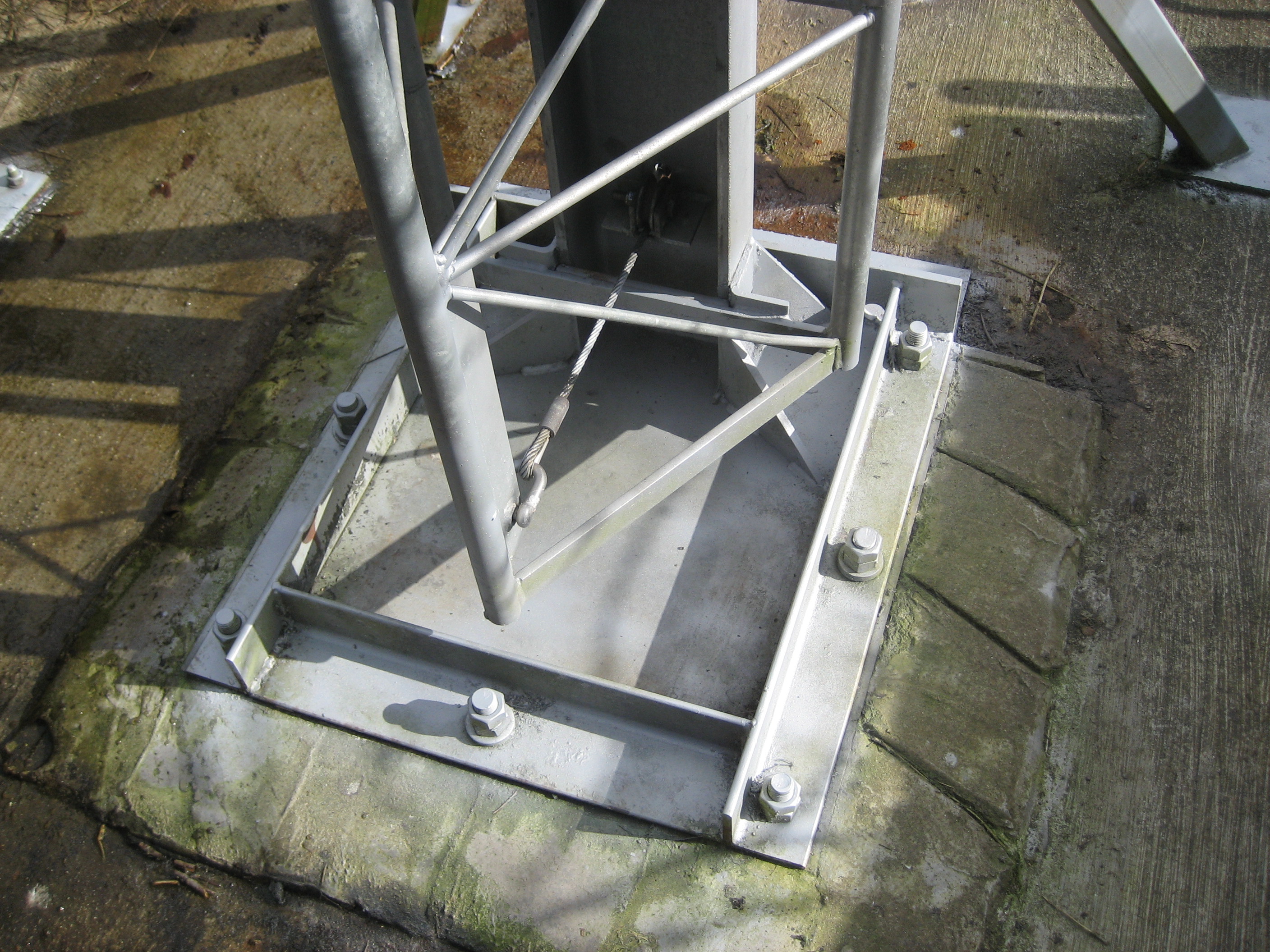
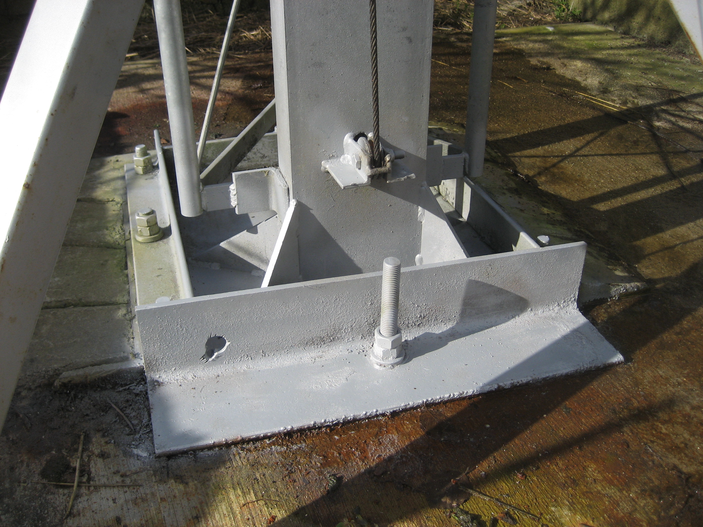
3. Four large supports made of 60mm x 60mm box section with individual base feet would be fabricated and welded to the base post. Two of them attached mid way up the post and the second pair attached at the top of the post. The theory was to spread the tower load between these "Super Gussets" as we named them and the original gussets, they would also greatly increase the support area. They would be strategically placed to protect the tower/ post from the prevailing winds which run from the south through west to north west.
Click Photos to enlarge
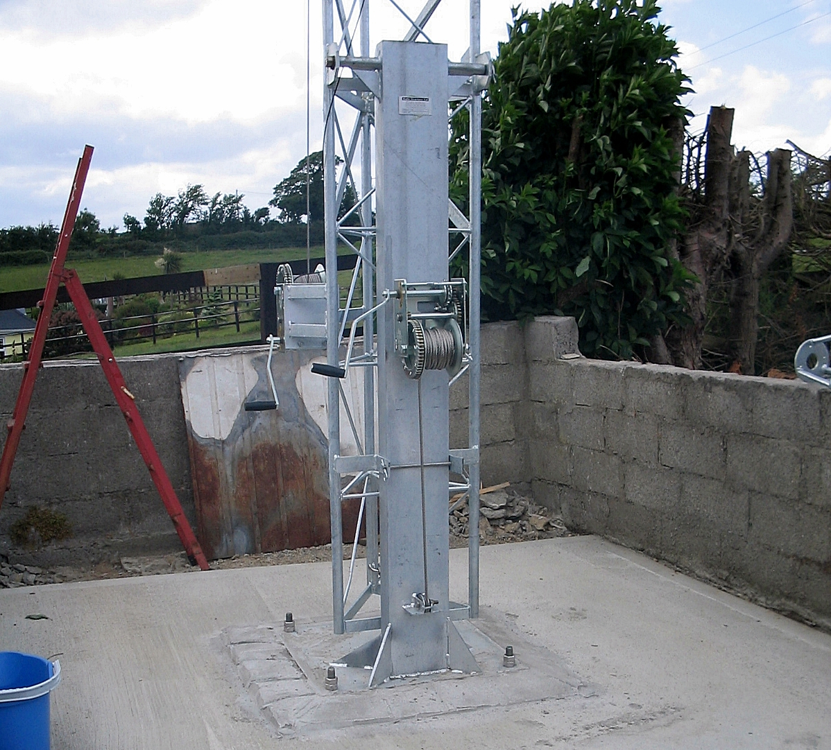
As originally supplied
|
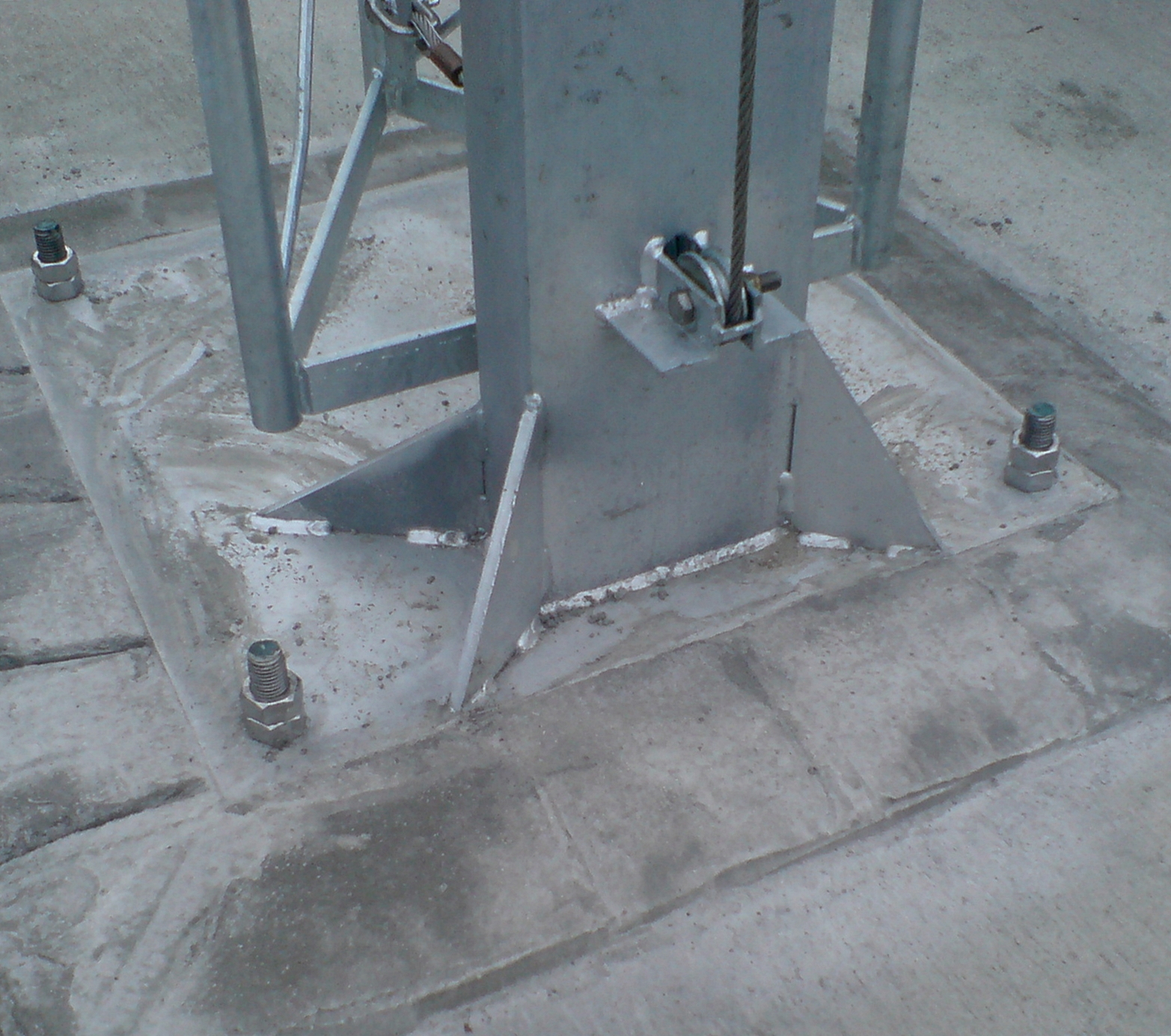
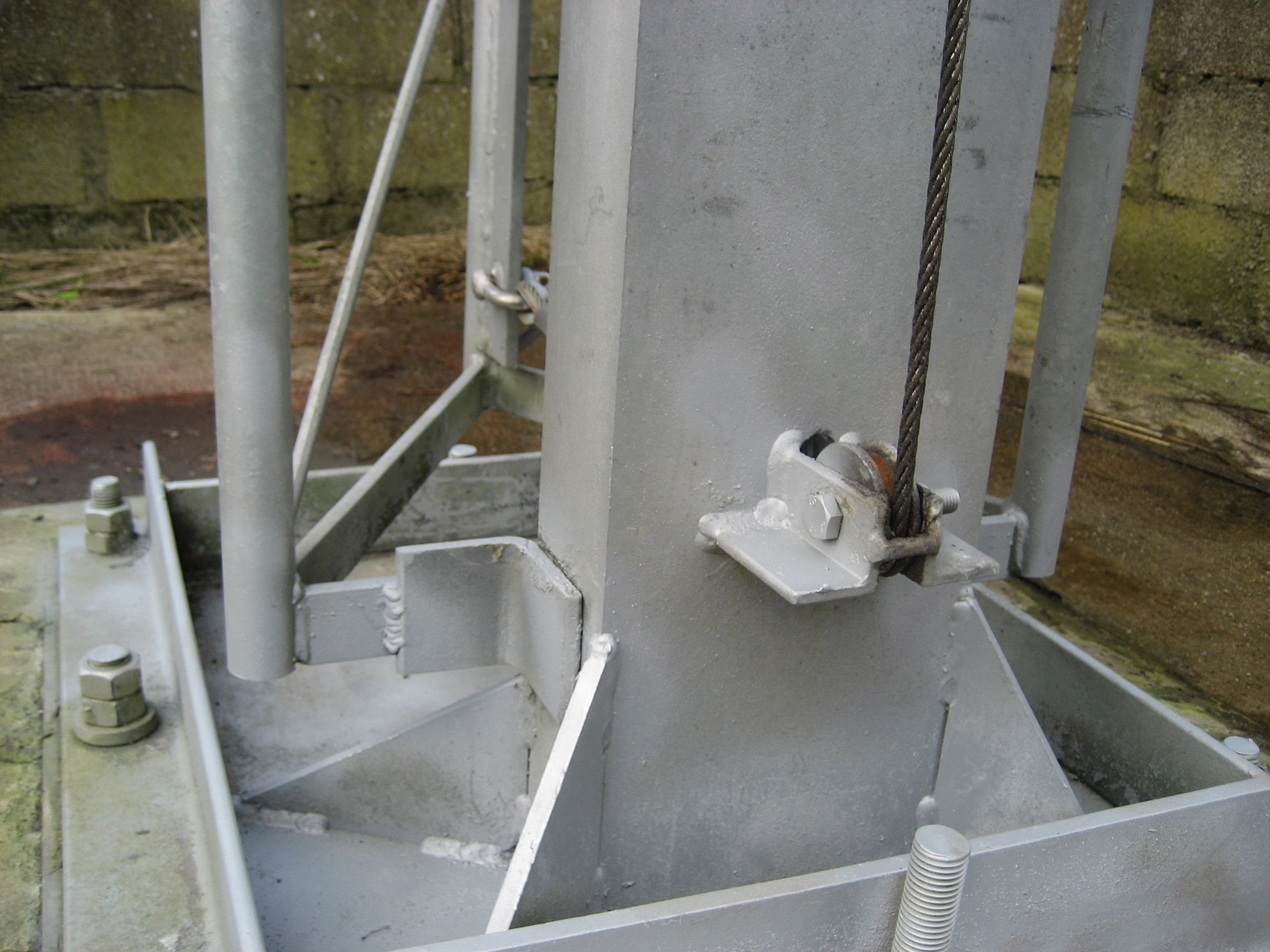
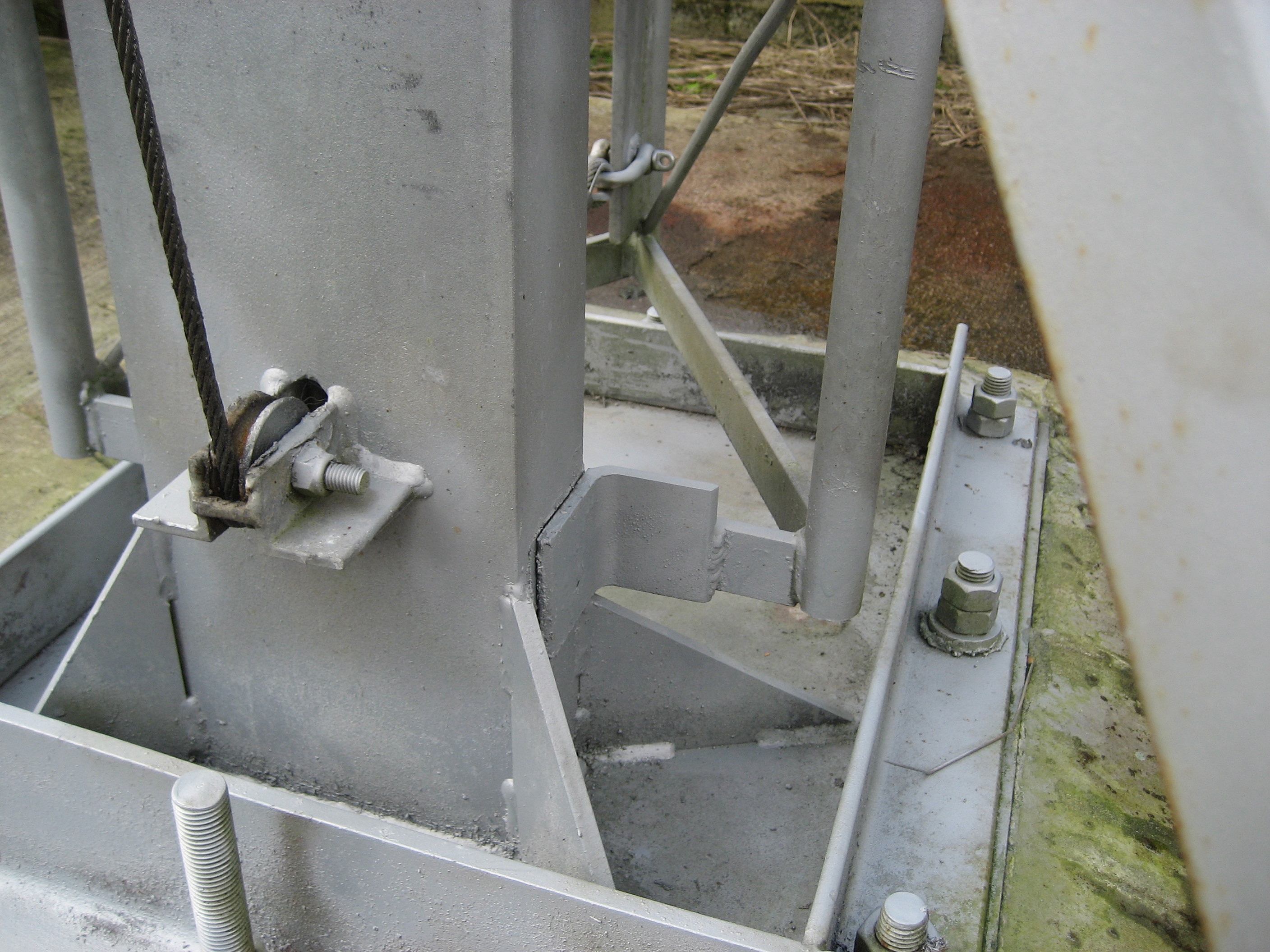
base close up
|
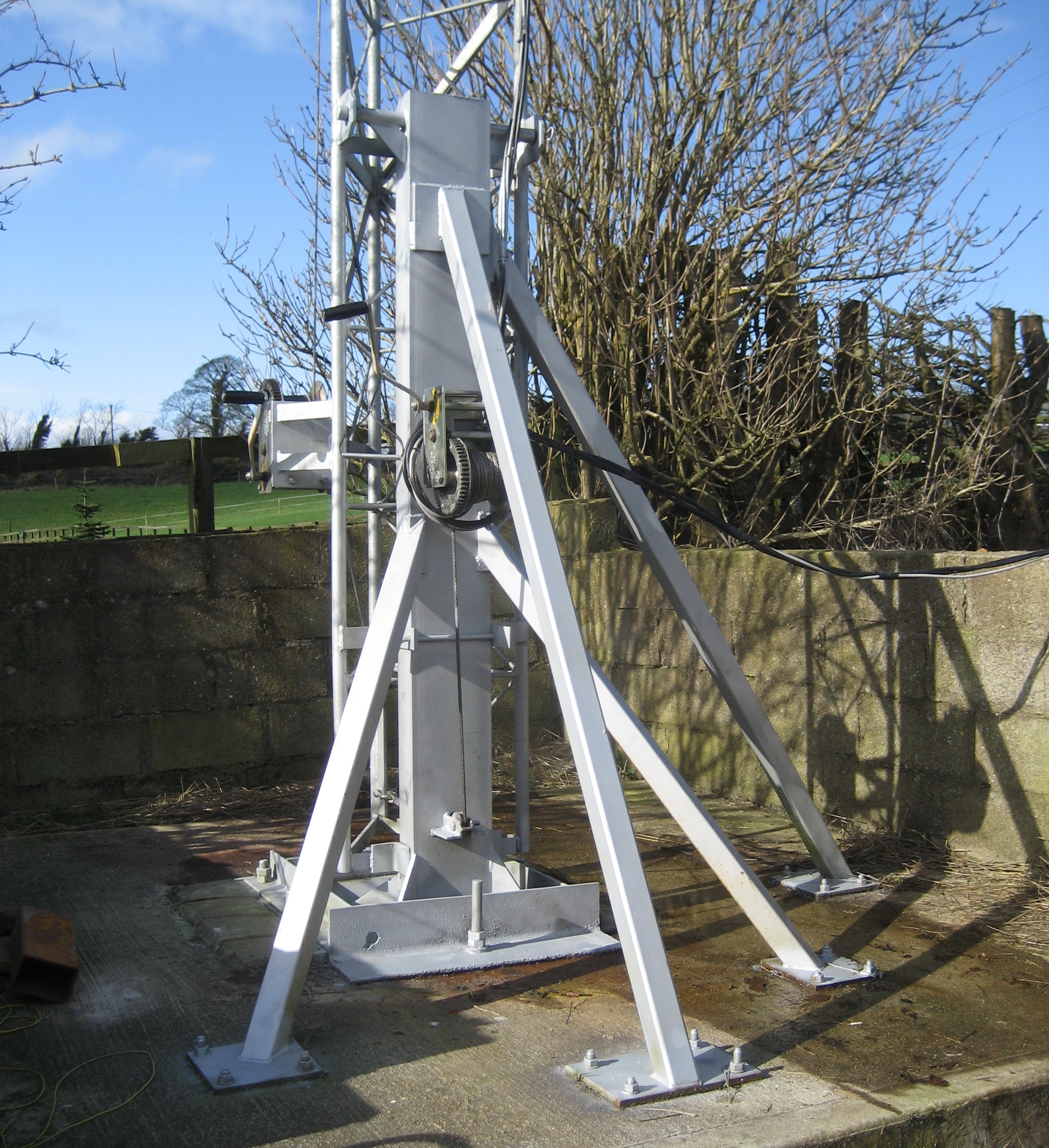
Base plate mods & Super gusset supports
|
Result !!!
After all the mods were carried out over a period of time I'm able to say that the improvement has been more than substantial. The rocking motion in the tower is gone even in blustery wind conditions. The base post now holds solid vertical.
This means that the tower does not lean in the wind from top to bottom like a stick been tipped over- the bottom section is now vertical and each of the four sections above it can use their entire length to take the load. Yes is does bend as any tower should, especially one of a crank up or telescopic nature. That was the issue because of the lightweight base it was unable to bend correctly through its length from a rigid vertical base post - all it could do was lean in a precarious manner. This is not to say that the above modifications are a necessary requirement. I did operate the tower at full height as it came from the factory but I was not happy with the performance. It was ashame to have to burn the galvanise where the work took place however these areas have been treated with metal protectants and cold galv spray, they will be monitored at regular intervals from now on. The base too is not as sleek a finish as before what with the extra angle and "super gussets" etc but I felt it necessary to carry out the work. The tower now performs very well even throughout the winter months. In the case of a very severe weather system I usually reduce the height to 50-65ft. In the future I may redesign the complete base plate and post. After examining the Versatower base design something similiar in a heavy duty version may be next. |
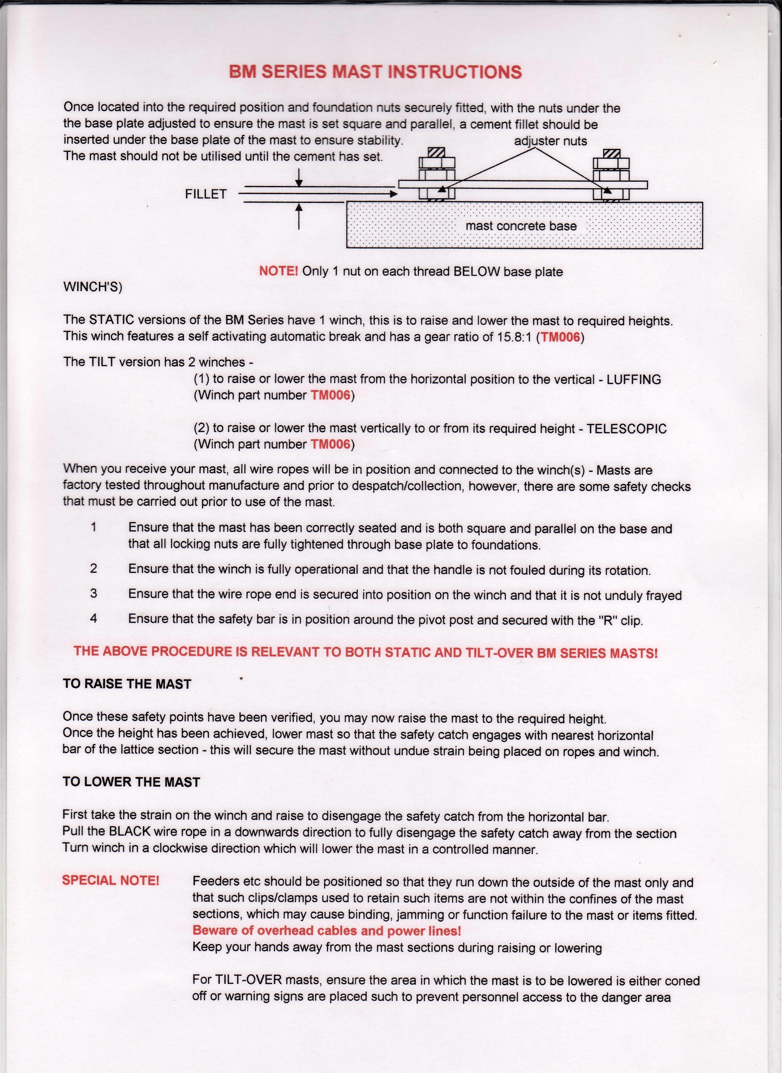
BM30 T Instruction Manual
|
|
If your a glutton for punishment you may like to know that one last thing to was done to put this to bed. Two small pieces of angle were welded onto the tower (at the very base of the of the bottom section) they may be best described as feet. They come out from the lowest horizontal plate and snuggly intersect either side of the post. Their job is to assist in holding the very base of the tower parallel to the base post or to use the "local vernacular" to stop the arse of the tower from kicking out!
|
|
* IMPORTANT NOTICE*
Crank up and tilt over type towers have many advantages for the radio amateur however due to the nature of their workings they need to be maintained to a very high standard. All aspects of their operation and structural integrity should be inspected throughly at regular intervals. THIS IS A BASIC REQUIREMENT. Failure to do so can result in serious injury, death or damage to property. I DO NOT RECOMMEND OR SUGGEST IN ANY WAY THAT THE INFORMATION ON THIS PAGE BE USED FOR OTHER INSTALLATIONS. THEY ARE SHOWN PURELY FOR INFORMATIVE PURPOSES AND TO RELATE PERSONAL EXPERIENCE
Crank up and tilt over type towers have many advantages for the radio amateur however due to the nature of their workings they need to be maintained to a very high standard. All aspects of their operation and structural integrity should be inspected throughly at regular intervals. THIS IS A BASIC REQUIREMENT. Failure to do so can result in serious injury, death or damage to property. I DO NOT RECOMMEND OR SUGGEST IN ANY WAY THAT THE INFORMATION ON THIS PAGE BE USED FOR OTHER INSTALLATIONS. THEY ARE SHOWN PURELY FOR INFORMATIVE PURPOSES AND TO RELATE PERSONAL EXPERIENCE
